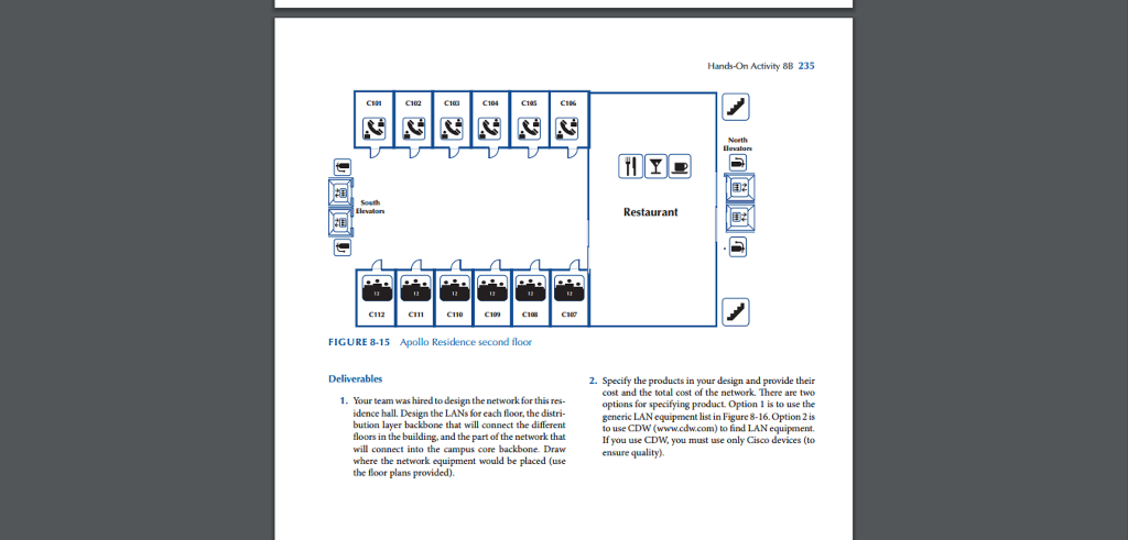
Design The Lans For Each Floor The Distribution Layer Backbone
Network Design With Examples Core And Distribution Router Switch Blog

Distribution Layer Functionality Network Design
Medium Enterprise Design Profile Reference Guide Medium Enterprise Design Profile Medp Lan Design Design Zone For Security Cisco
Campus Wired Lan Designs 1 1 Lan Design Cisco Press

Backbone Design In Computer Network

Network Design Models Do I Know This Already Quiz Cisco Press
Draw where the network equipment would be placed use the floor plans provided 2.
Design the lans for each floor the distribution layer backbone.
Apollo Residence Network Design Using Smartdraw Chegg Com

What Are Industrial Communication Networks An Overview Communication Networks Networking Communication
Https Www Cisco Com C Dam Global Shared Assets Pdf Cisco Enterprise Campus Infrastructure Design Guide Pdf
Cisco Virtualized Multi Tenant Data Center Version 2 0 Large Pod Design Guide Design Considerations Support Cisco

Enterprise Network Design In Cisco Packet Tracer 6 1 1 Youtube
Hands On Activity 83 Apollo Residence Network Design Apollo Is A Luxury Residence Hall That Will Serve Honor Stu Dents At Your University The Course Hero
Vmdc 3 0 1 Design Guide Design Details Support Cisco

Cisco Templates To Get You Started Right Away Creately Blog Network Infrastructure Virtual Private Network Networking

Designing Switched Lan Internetworks
Structural Overview Of Isp Networks Springerlink

It Telecommunications And Networking Guideline Joint Information Environment
Cisco Virtualized Multi Tenant Data Center Version 1 1 Design And Deployment Guide Cisco Vmdc Design And Deployment Support Cisco

Siemens Ruggedcom Rs950g Compact Ethernet Switches In 2020 Siemens Switches Locker Storage

Types And Uses Of Backbone Networks Geeksforgeeks
Https Www Cisco Com C Dam En Us Products Collateral Security Dynamic Multipoint Vpn Dmvpn Dmvpn Design Guide Pdf
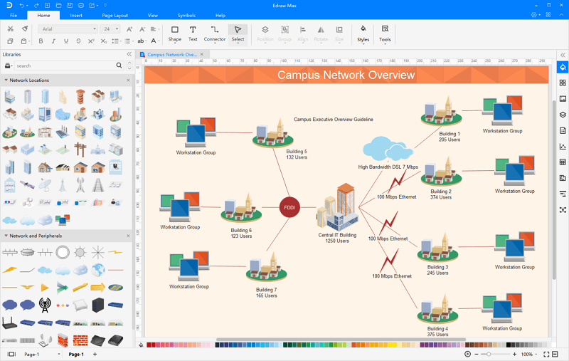
Campus Network Design Software Examples To Demo How To Design The Campus Network
Cisco And Hitachi Adaptive Solutions For Converged Infrastructure With Cisco Aci Design Guide Cisco
Flexpod Datacenter With Vmware Vsphere 6 5 Design Guide Cisco
Https Encrypted Tbn0 Gstatic Com Images Q Tbn 3aand9gcq4sxo02jc Xgxu3kcp4ejueluddwqta U3zkp21uoap O1b3et Usqp Cau

4 Local Area Network Technologies Designing Large Scale Lans Book
Https Assets Ext Hpe Com Is Content Hpedam A00004216enw
1 Structured Backbone Design Of Computer Networks Ppt Download

How To Install Network Infrastructure In Shared Buildings Gov Uk

Wiring Diagram Rj45 Connectors For Patch Cables Category 5 Wire New Cable On Wiring Diagram Ethernet Cable Ethernet Wiring Ethernet Cable Computer Science
Source : pinterest.com
